Understanding how DC voltages combine is quite simple. They add linearly when we wire sources (like batteries) in series. But understanding how AC waveforms combine is complicated. AC waveforms don’t always sum intuitively unless the peaks and valleys align perfectly. We see many examples where people interchange the terms phase and polarity. In reality, those words refer to different phenomena. Let’s take a close look at audio signal phase and polarity.
What Is an Audio Signal?
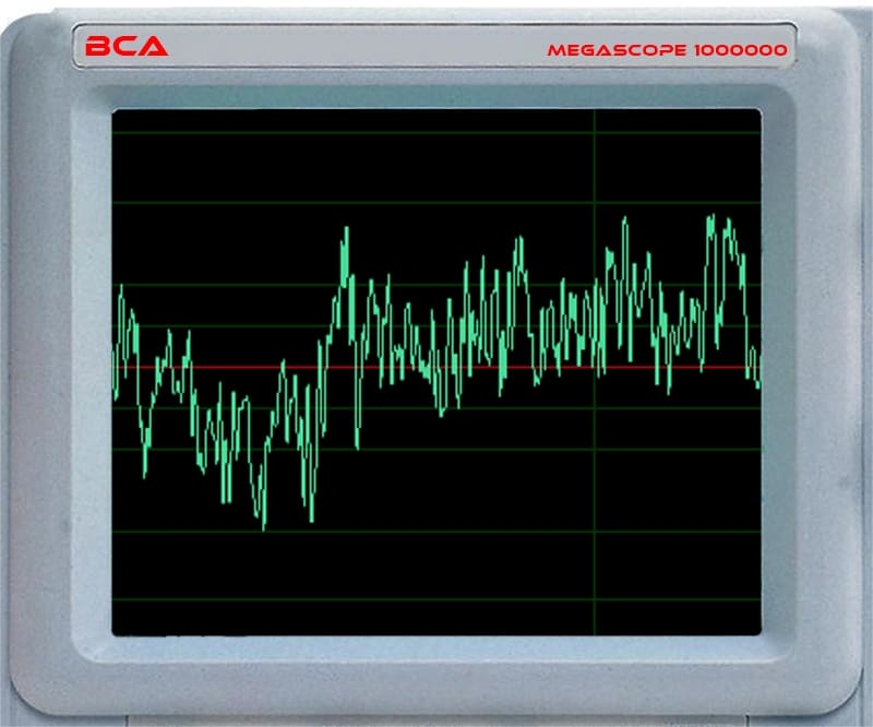
We will use sinusoidal waveforms as our example audio signals for this discussion. The sounds we hear are combinations of infinite frequencies. If you look at music on an oscilloscope, it would look something like the image below.
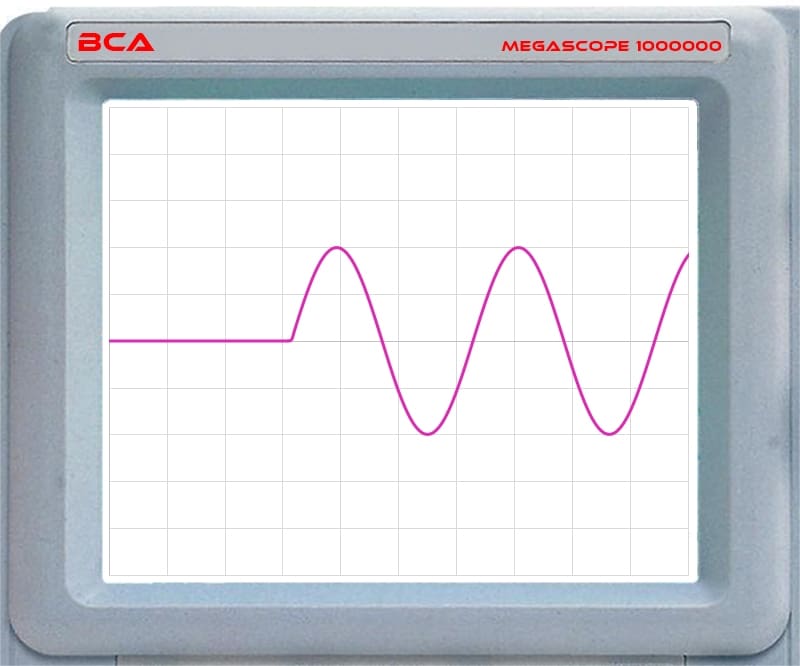
Phase refers to the relative timing between two waveforms. A single waveform can’t have phase. We must compare it to something else. As such, we will need a reference waveform for this article. You can see that below.
In Phase
Let’s start with the basics. When we describe two waveforms as “in phase,” we infer that the peaks and valleys are aligned. The starting point of the waveform should happen at the same time. The image below shows two waveforms that are “in phase.”
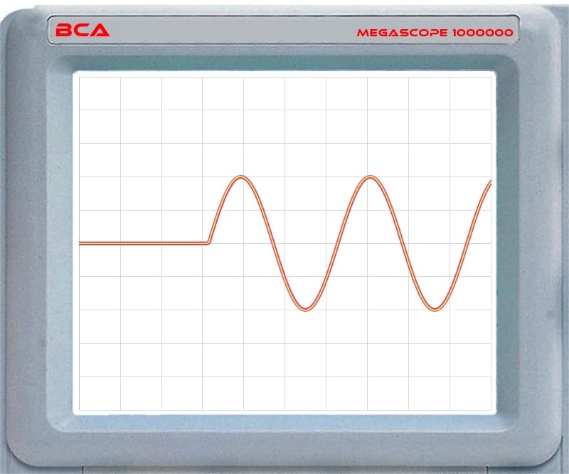
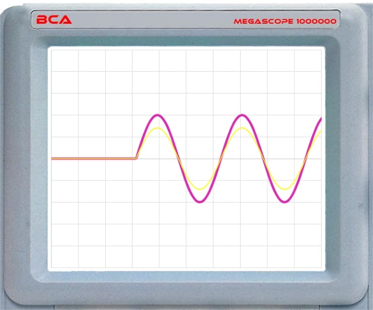
Two waveforms can be in phase but have amplitude differences. The image below shows that condition.
Reverse Polarity
We often see amplifiers with a switch that inverts the polarity of the audio signal passing through the devices. These are frequently and mistakenly labeled as “Phase.” Let’s explain.
Phase is the relative difference in time between two signals. Polarity refers to a contrasting waveform direction. In DC voltage, we know that if we put a voltmeter’s red lead on the battery’s positive terminal and the black lead on the negative, we’ll see a positive voltage. If we reverse the leads and put the red on the negative and the black on the positive, we’ll see a negative voltage on a digital meter. We call this “having the polarity backward.”
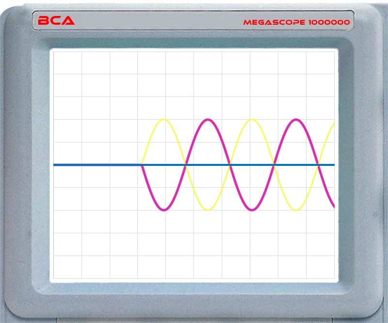
In AC waveforms, the same thing happens. If two waveforms have the same starting point and frequency, but one goes positive while the other goes negative, we refer to one being in the opposite polarity.
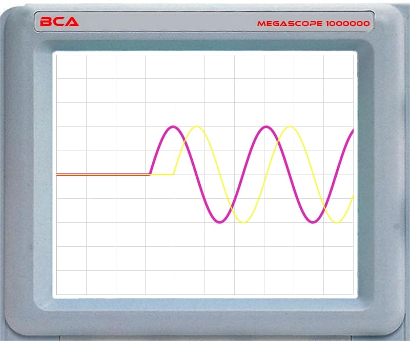
Here are our two audio waveforms in the oscilloscope. The yellow waveform shows the opposite polarity to that of the pink waveform.
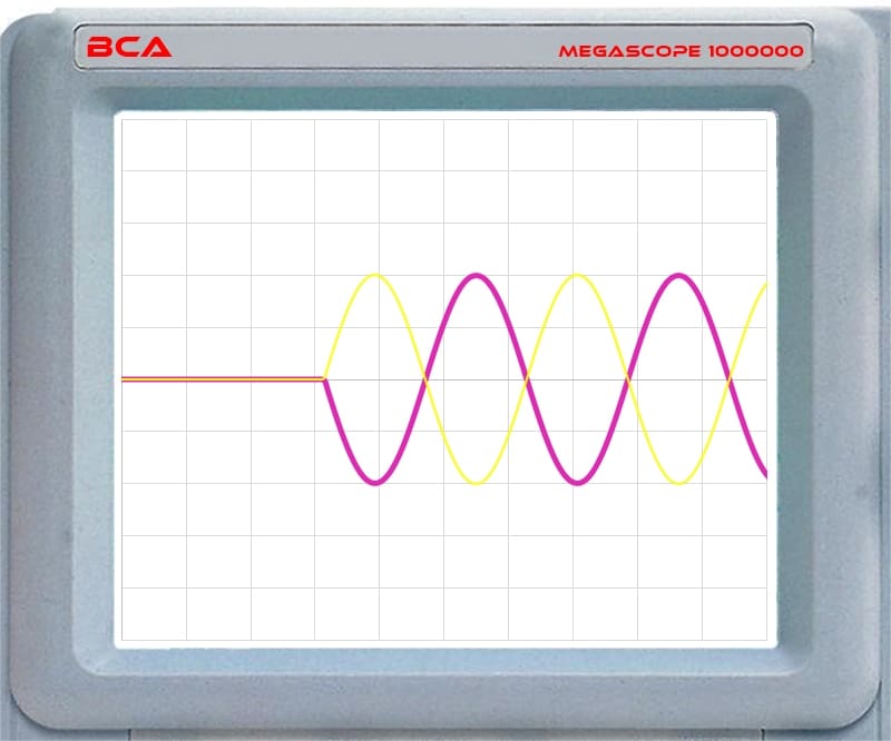
Let’s consider this in terms of audio signals going to a speaker. The speaker driven by the yellow signal would start from rest and then initially move forward. The speaker driven by the pink signal would begin moving toward the magnet. Activating the polarity switch has the same effect as swapping the positive and negative speaker wire connections.
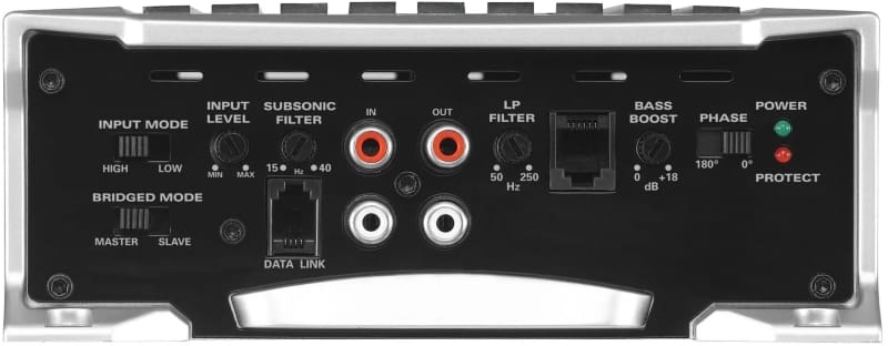
The image above shows an amplifier with the polarity control switch incorrectly labeled as phase. As a bonus, the amplifier has the infrasonic filter incorrectly marked Subsonic. This labeling is a fairly common error.
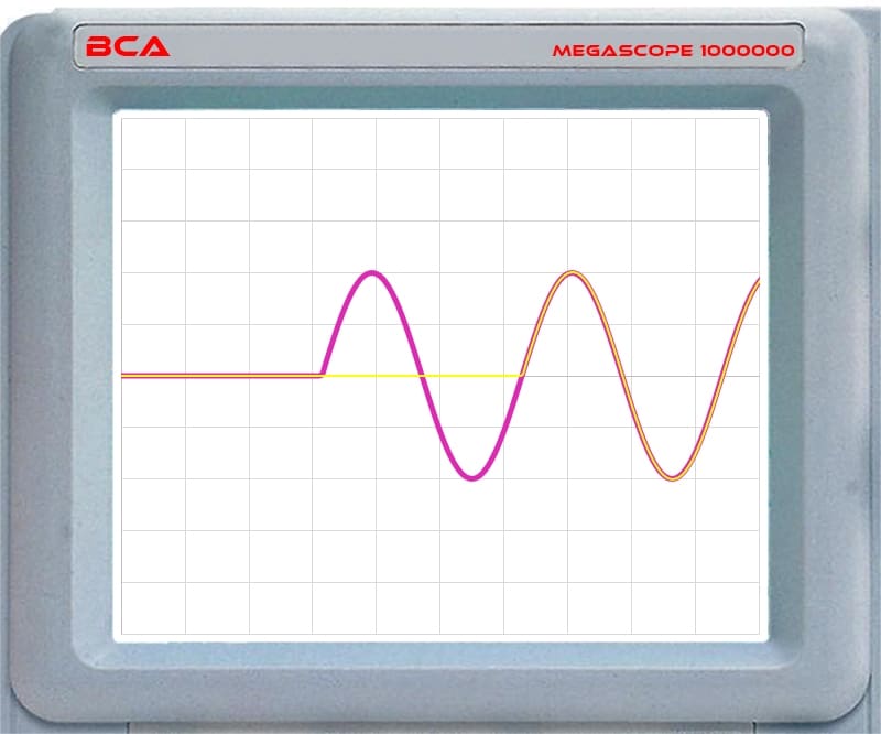
If the above amplifier could adjust the phase of the waveform of one signal to be 180 degrees from the other, the waveforms would look like this:
Phase
When discussing phase shifts, we include the peaks and valleys of a waveform and the starting time. This start point or time is especially crucial to discussing audio signals that are never sinusoidal. The starting times move if there is a phase shift between two signals. A difference in starting times implies a delay on one of the waveforms. We can do this quickly and deliberately with a digital signal processor. Adding delay is common in “time aligning” the left and right speakers in a stereo sound system.
Electricians and engineers often discuss phase angles in AC waveforms when driving inductive loads like electric motors. In these cases, the voltage applied to the motor may be “out of phase” with the current flowing through the motor. The same thing happens with speakers and passive crossover networks. These components’ reactive elements (inductance and capacitance) can cause the current and voltage to be “out of phase.” These phase shifts are why we can’t accurately measure the power out of an amplifier without measuring the phase angle between current and voltage. If that was confusing, don’t fret. These are concepts that engineers and technicians learn about in college.
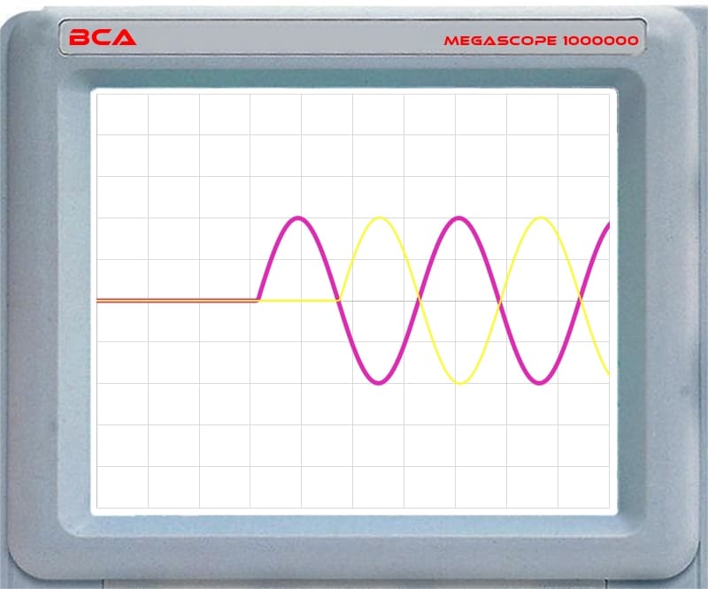
We often talk about degrees when discussing the phase of two waveforms. One complete cycle of a sine wave is 360 degrees. A half-cycle is 180 degrees. The angle between when the sine wave initially moves from the 0-volt level to the first peak is 90 degrees. Here is an example of a 90-degree phase shift between two waveforms:
Here’s what a 360-degree phase shift looks like:
Understanding that the starting points of the two waveforms differ is crucial to understanding how audio waveforms interact. If you were to “align” the peaks and valleys, we’d think these signals were “in phase.” This practice is a common issue for people who try to “time align” a subwoofer to a midbass speaker by reversing the polarity of one relative to the other, then adjusting a delay so there is a sizeable acoustic null shown on an RTA at the crossover frequency. This practice doesn’t consider the start time of the audio signals. Considering phase and start time is required to deliver a system where the sound from the subwoofer arrives at the listening position at the same time as the midbass or midrange drivers.
Why Are Signal Phase and Polarity Important in Car Audio Systems?
For people who’ve upgraded their vehicles with a radio and two pair of speakers, the primary concern is that the acoustic polarity of all the speakers in the system is the same. When a speaker produces a sound, it should combine acoustically with the output of other speakers in the system. You can test this quickly without any special tools.
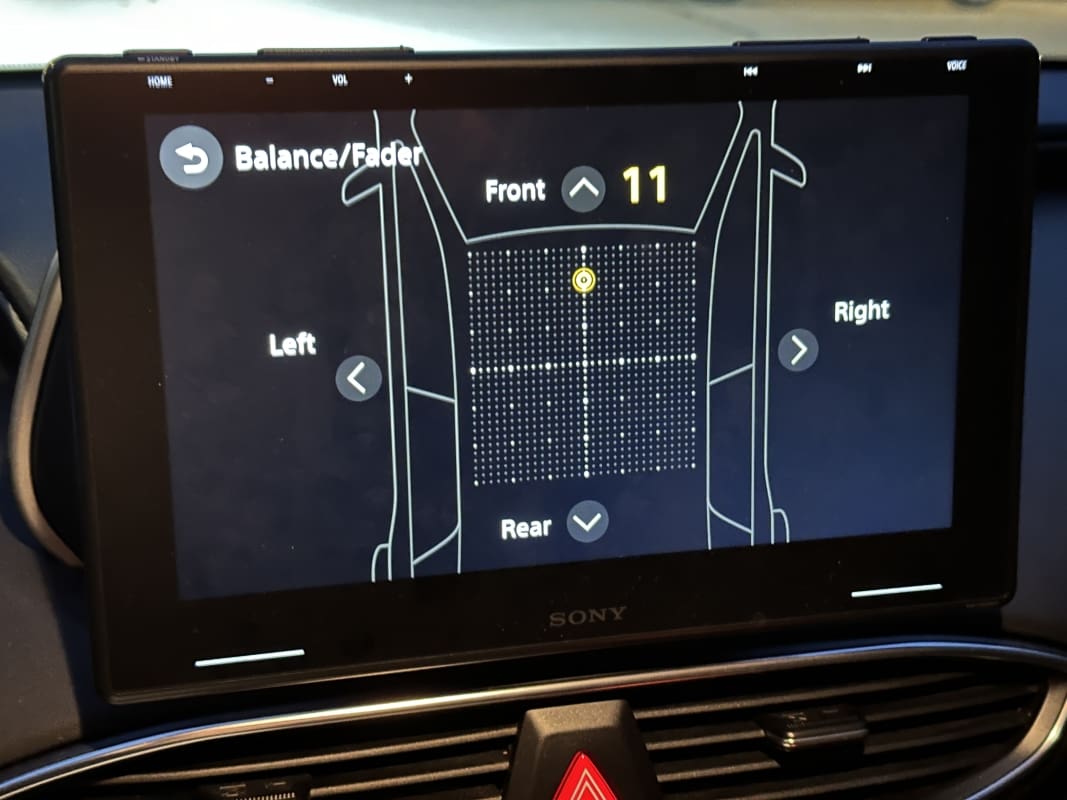
Play music with a reasonable amount of bass. Use the balance and fader controls to listen to one speaker at a time. Start with the front left speaker. Now, use the balance to add the front right speaker so both play. The relative bass level should increase when you add the second speaker. If it doesn’t, the wiring likely has a polarity problem.
Repeat the test with the front left speaker playing, then use the fader control to add the left rear speaker. Once again, the bass should increase. If it does, fade rearward so only the left-rear speaker is playing. Now, use the balance control to add the right-rear speaker. Once again, we should get more bass. If the bass decreases when a second speaker plays, drop by a local specialty mobile enhancement retailer and ask them to check the wiring.
Signal Summing and Cancellation
Sometimes the distances between speakers cause incomplete summing of all frequencies. Let’s go back to looking at audio waveforms for a second. If two signals have the same amplitude, frequency content and starting times, how they add together (called summing) is predictable.
In the example above, the signals combine perfectly and the total amplitude doubles. An example would be listening to music at home on a set of stereo speakers and sitting equidistant from both speakers. When it’s perfect, or at least pretty good, signals that are equal in amplitude and in phase in both channels appear to come from a spot between the speakers. Some call this a “phantom center image.” It’s just how stereo recording works and doesn’t require a fancy name.
Let’s look at how signals with different phase relationships sum. First, let’s look at two waveforms, of which one is reversed in polarity.
If one speaker moves outward and the other moves inward, their output should cancel. If you have a pair of subwoofers and one is wired backward, the result is that the system produces no bass.
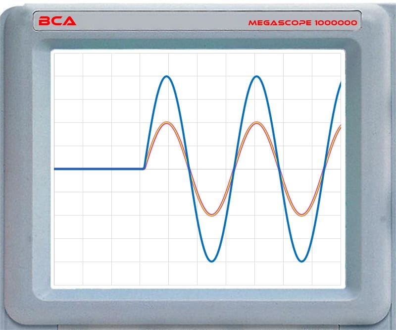
Now, what happens when one signal arrives before another? Here are the waveforms if one signal lagged the other by 90 degrees:
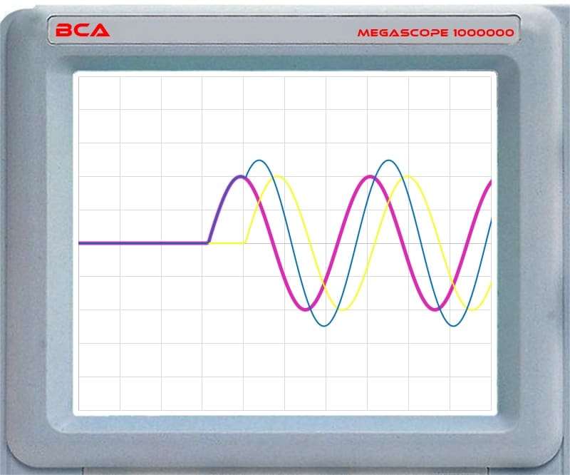
A few bad things happen when signals don’t start simultaneously. In terms of the combined waveforms, the amplitude only increases by 25% instead of 100%. This happens if you’re at home, sitting much closer to one stereo speaker than the other. The same happens in your car, where the left door speaker is maybe 30 inches away, and the right is 45 inches away.
Audio Content and Signal Summing
Remember, music is not a single frequency, as we’ve shown in the oscilloscope plots. It’s a combination of thousands of frequencies. We don’t talk about the phase between audio signals; we talk about delay times. Every frequency has a different wavelength. So if there is a timing difference between the signals, some frequencies combine, and others cancel. The result produces an uneven frequency response.
Let’s combine some signals in Adobe Audition to demonstrate this.
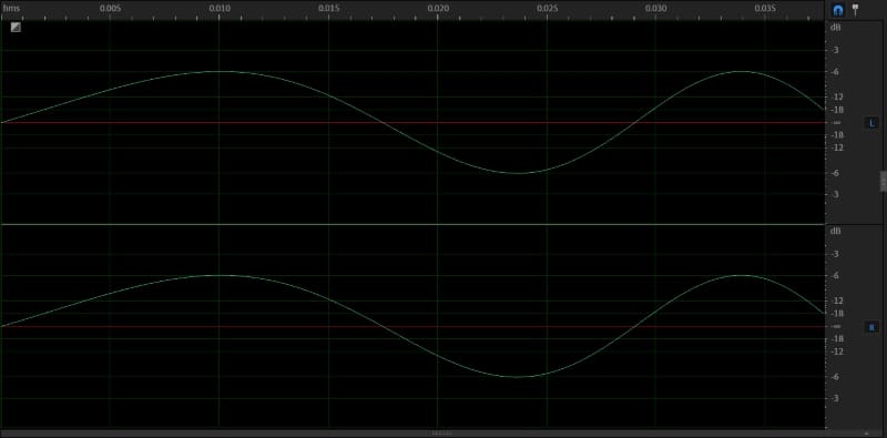
I created two sine sweeps. These are 20-second tracks that start at 20 Hz and increase in frequency by 20 kHz. The image below shows that the left and right channels are equal in amplitude and phase.
Let’s look at the frequency response of the two signals:
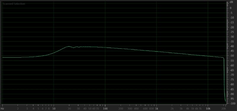
The frequency response graph isn’t perfectly flat because I don’t have control over the speed at which the sweep occurs. In short, the bass is present for longer than the highs. What you need to know is that the response is flat and smooth.
Let’s add about 1.7 milliseconds of delay to the right channel waveform. This is the time it takes sound to travel about 24 inches. That’s not an uncommon path length difference between a vehicle’s left and right speakers.
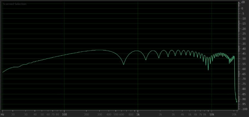
As you can see, the results are dramatic. The frequency response is full of dips. We call this comb filtering, which happens when two sound sources are at different distances from the listening or measuring position. This could be attributed to path length differences between speakers or to a speaker’s sound reflecting off a surface and recombining with the direct-path sound. If there are path length differences, your installer can use a digital signal processor to delay the signal to the closer speaker. There isn’t much you can do about reflections other than to relocate the speakers.
Audio Signal Phase and Polarity
We hope this serves as a primer to help you understand the concepts of audio signal phase and polarity. A solid understanding of these concepts is crucial to designing and calibrating car audio systems that sound amazing. If you want better sound from your car audio system, drop by a local specialty mobile enhancement retailer today. Ask to hear one of their demo vehicles and discuss the options for improving your vehicle’s stereo.
This article is written and produced by the team at www.BestCarAudio.com. Reproduction or use of any kind is prohibited without the express written permission of 1sixty8 media.

Leave a Reply